Akai MAX25 User's Guide Page 6
- Page / 88
- Table of contents
- BOOKMARKS
- User Guide (English) 3
- Features 4
- Top Panel 4
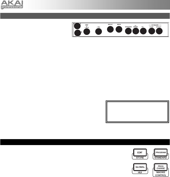
- Rear Panel 6
- Edit Mode 7
- Touch Faders 8
- S-Switches 8
- Arpeggiator 10
- Note Repeat 10
- Sequencer 11
- Transport Controls 11
- Program Mode 12
- Global Mode 12
- Program Change Mode 14
- Vyzex Editor 17
- AkaiConnect 17
- Guía del usuario (Español) 18
- Características 19
- Panel superior 19
- Panel Trasero 21
- Modo de edición 22
- Faders táctiles 23
- Interruptores S 23
- Arpegiador 25
- Repetición de notas 25
- Secuenciador 26
- Controles de transporte 26
- Modo de programa 27
- Modo Global 27
- Modo de cambio de programa 29
- Editor Vyzex 32
- CV (voltaje de control) 32
- Contenu de la boîte 33
- Caractéristiques 34
- Panneau supérieur 34
- Panneau arrière 36
- Edit Mode (Mode d’édition) 37
- Arpeggiator (arpégiateur) 40
- Sequencer (séquenceur) 41
- Global Mode (mode général) 42
- Créer et jouer un séquence 46
- Logiciel AkaiConnect 47
- Contenuti della confezione 48
- Caratteristiche 49
- Pannello superiore 49
- Pannello posteriore 51
- Modalità 51
- Modalità Edit 52
- Fader Tattili 53
- Interruttori S 53
- Arpeggiatore 55
- Sequenziatore 56
- Comandi di trasporto 56
- Modalità Program (programma) 57
- Modalità Globale 57
- Benutzerhandbuch (Deutsch) 63
- Funktionen 64
- Oberseite 64
- Rückseite 66
- Bearbeitungsmodus 67
- Touch-Fader 68
- S-Schalter 68
- Noten-Wiederholung 70
- Transportsteuerungen 71
- Programm-Modus 72
- Global-Modus 72
- Programmänderungs-Modus 74
- Vyzex-Editor 77
- Appendix (English) 78
- MIDI Implementation Chart 81
- USB Ports A & B 81
- USB Port C (MIDI) 82
- USB Port D (Mackie Control) 83
- USB Port E (Remote) 84
- Technical Specifications 85
- 7-51-0393-A 88
Related products and manuals for DJ controllers Akai MAX25


 (40 pages)
 (46 pages)
(44 pages)
(56 pages)
(45 pages)
(24 pages)
(44 pages)
(219 pages)
(25 pages)
(266 pages)
(292 pages)
(9 pages)
(46 pages)
(74 pages)
(313 pages)
(4 pages)
(24 pages)
(54 pages)
(18 pages)
(46 pages)
(44 pages)
(56 pages)
(45 pages)
(24 pages)
(44 pages)
(219 pages)
(25 pages)
(266 pages)
(292 pages)
(9 pages)
(46 pages)
(74 pages)
(313 pages)
(4 pages)
(24 pages)
(54 pages)
(18 pages)
© 2020, manymanuals.com. All rights reserved. | 0.660 s |
 Manymanuals.com
 Manymanuals.de
 Manymanuals.fr
 Manymanuals.it
 Manymanuals.pl
 Manymanuals.cz
 Manymanuals.es
 Manymanuals-pt.com
Comments to this Manuals