Akai DR16 pro Operator's Manual Page 29
- Page / 167
- Table of contents
- BOOKMARKS
- Operator’s Manual 1
- Important Notice 2
- Page iii 4
- IMPORTANT 5
- Contents 8
- Page viii 9
- Introduction 10
- What is the DR16pro? 10
- Signal Flow 12
- Description of Signal Flow 13
- Level Diagram 14
- Inside the DR16pro 15
- Front and Rear Panels 16
- 1: Front and Rear Panels 17
- 11 12 13 14 15 16 19
- 17 18 19 20 20
- EDIT MIX 21
- 27 28 29 30 22
- 31 33 34 35 36 37 23
- 40 41 42 43 44 25
- 45 46 47 48 25
- 51 52 53 5554 26
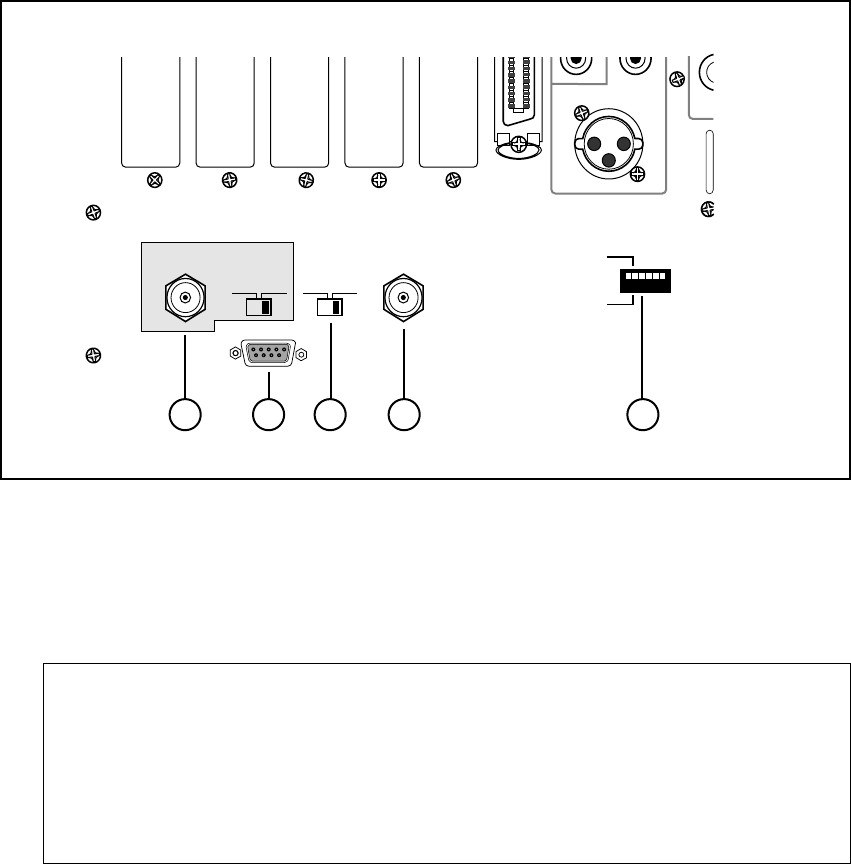
- Rear Panel 27
- 5 76 8 9 29
- 12 13 13 14 15 13 30
- 16) SIGNAL GROUND 31
- 17) Power inlet 31
- Getting Around the DR16pro 32
- Operation 33
- Setting Parameters 34
- Entering Time Values 35
- 2: Getting Around the DR16pro 36
- “in” or “out” points 36
- Setting Up the DR16pro 37
- Typical DR16pro Setup 38
- Recording 39
- 4: Recording 40
- Selecting the Bit-Length 41
- 20-Bit Packed Audio 41
- Input Source 42
- Selecting the Input Channels 44
- Using the BUS function 45
- Set the destination tracks: 46
- Set the source tracks: 46
- Bus Function Notes 46
- Arming Tracks 47
- Punch-In Functions 48
- Footswitch Punch-In/Out 49
- Track Number Limitations 51
- Monitoring 51
- Mute Stop Mode 52
- Rehearsal 52
- Recording Undo 53
- Setting the Recording Mode 54
- To set the recording mode: 55
- DESTRUCT 55
- Playback 56
- Digital Audio Formats 57
- To start playback: 57
- The TO key 58
- The FROM key 59
- The OVER key 60
- The IN->OUT key 60
- Using Repeat to Punch-in 61
- Varispeed 62
- Projects 63
- Loading Project Files 64
- Deleting Project Files 65
- 6: Projects 66
- Project save 68
- Output Assignment Mode 69
- Track Swapping 69
- Individual Channel Settings 70
- Setting the Pan 71
- Setting the Send Levels 71
- Selecting the Bus Send 72
- Setting the Fade 72
- Setting an Auxiliary Input 73
- System Settings 74
- Adjusting the Master Level 74
- Selecting Mono or Stereo Send 75
- Selecting Pre- or Post- Send 76
- Snapshot Settings 77
- Recalling a Snapshot 77
- Mapping Snapshots 78
- Inserting Snapshots 79
- Erasing Snapshot Locations 79
- CHANNEL ON 80
- 2/10 3/11 4/12 5/13 6/14 7/15 80
- ADAT Digital Output 81
- Take Functions 82
- Checking a Take 83
- Committing a Take 83
- Deleting a Take 84
- Other Take Applications 85
- Locate Functions 86
- Storing Direct Locate Points 87
- Stack Locate Points 88
- Recalling Stack Locate Points 88
- Last Memory 89
- Setting the Preroll Time 90
- Time Display 91
- Setting Relative Time to Zero 92
- Section Copy 95
- Executing the Copy 97
- Insert track 100
- After insert 100
- Insert point 100
- After erase 101
- Erase Track 101
- Delete Track 102
- After delete 102
- 11: Editing 103
- Hard Disks 105
- Hard Disk Size 106
- Total length of SCSI cables 107
- SCSI Termination 108
- Checking for Disks 109
- 12: Hard Disks 110
- Page 101 110
- Formatting Disks 111
- Erasing Disks 113
- Optimizing Your Hard Disks 114
- Copying Disks and Projects 116
- Disk Copy Notes 117
- Copying a project 117
- Software Write Protect 118
- Backup and Restore 119
- Backup to multiple tapes 121
- Backup of multiple disks 122
- Verifying backup data 122
- Restoring from multiple tapes 123
- 13: Backup and Restore 124
- Page 115 124
- Loading from DAT 125
- Restoring the Backup 125
- To load from multiple tapes: 126
- Restore Notes 126
- Synchronization 127
- SMPTE/EBU Synchronization 127
- 14: Synchronization 128
- Page 119 128
- Master Synchronization Notes 129
- MIDI Synchronization 130
- MIDI Timecode Synchronization 131
- MIDI Clock Synchronization 131
- About MIDI Machine Control 132
- Page 124 133
- RS422 FULL SLAVE Setup 134
- Digital Audio Sync 135
- Song Mode 136
- Tempo and Beat Map 137
- Creating a Song 138
- Setting the Beat 139
- To check the Beat map: 140
- Creating a Tempo Map 141
- To check the Tempo map: 142
- Other Functions 143
- Saving Settings to Flash ROM 144
- 16: Other Functions 145
- Page 136 145
- Page 137 146
- Setting the Mute Controller 147
- Setting the Level Controller 147
- Setting the Pan Controller 148
- Setting the Bus Controller 148
- Setting the Master Controller 148
- Setting the Fade Controller 149
- Setting the Device ID 149
- To use the MT8: 149
- Page 141 150
- Appendix 151
- Specifications (Continued) 152
- Multi-AES/EBU 153
- 17: Appendix 154
- Page 145 154
- IB -808G Block Diagram 155
- System Error Codes 156
- Page 148 157
- Page 149 158
- Page 150 159
- Page 151 160
- MIDI Implementation Chart 161
- 18: Index 162
- Page 153 162
- Page 154 163
- Page 155 164
- Page 156 165
- Page 157 166
- Yokohama, Japan 167
Related products and manuals for Digital Video Recorders (DVR) Akai DR16 pro
 (2 pages)
© 2020, manymanuals.com. All rights reserved. | 0.069 s |
 Manymanuals.com
 Manymanuals.de
 Manymanuals.fr
 Manymanuals.it
 Manymanuals.pl
 Manymanuals.cz
 Manymanuals.es
 Manymanuals-pt.com
Comments to this Manuals