Akai Multi Video Processor RMD-V3104U User Manual Page 8
- Page / 49
- Table of contents
- TROUBLESHOOTING
- BOOKMARKS
- RMD-V3104U 1
- INTRODUCTION 2
- PRECAUTIONS UPON USE A 3
- INSTALLATION PRECAUTIONS 4
- FEATURES 5
- TYPICAL SETUP 6
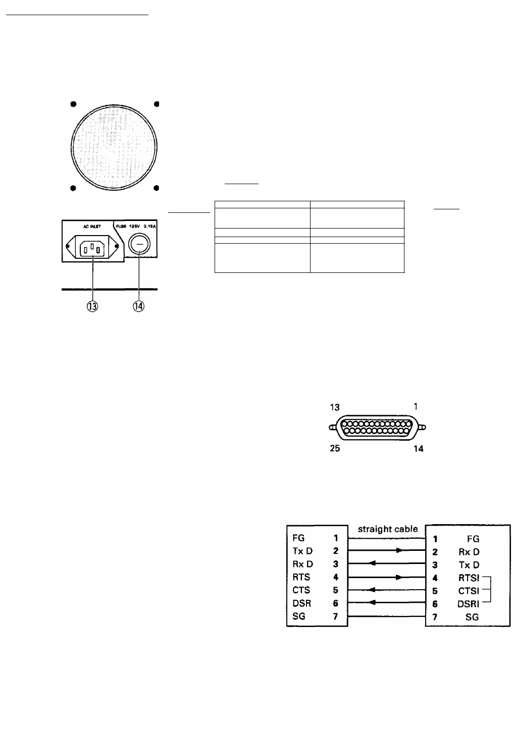
- REAR PANEL 8
- CONTROLS AND CONNECTORS 10
- 1. Features 11
- TROUBLESHOOTING 12
- SPECIFICATIONS 13
- 1. introduction 14
- MVP MANUAL 15
- 15
- 4. OPERATING MODES 17
- 5. MVP VIDEO OUTPUT MODES 19
- 6. ADJUSTMENT FUNCTIONS 20
- 1. Command reference 21
- For your safety 32
- (1) Outline of the RMD-V3020 34
- (2) VS board command rules 35
- [HPS, VPS commands] 38
- [HWN, VWN commands] 39
- [HWD, VWD commands] 39
- (19) Model fresh [F command] 43
- (25) All reset [ARS command] 46
- 11. MODE 99 47
- 12. VS BOARD MODEL SELECTION 48
© 2020, manymanuals.com. All rights reserved. | 0.787 s |
 Manymanuals.com
 Manymanuals.de
 Manymanuals.fr
 Manymanuals.it
 Manymanuals.pl
 Manymanuals.cz
 Manymanuals.es
 Manymanuals-pt.com
Comments to this Manuals